| |
| Why Choose A Toroidal
Transformer? |
|
|
| In the past,
only the most exotic power application justified the use
and cost of a toroidal transformer, as they were in
limited supply due to the cost of winding toroidals.
However, technical advances in winding and production
techniques have lowered the cost and increased the
availability of toroidal transformers, making them a
desirable and cost-efficient alternative to laminated
transformers in a wide variety of applications.
|
| |
| Benefits of Toroidal Transformer
Design |
|
|
Efficiency: The toroidal form
of transformer offers excellent efficiency for a given
size and weight.
The toroidal core provides
a virtually perfect magnetic circuit, eliminating the
inherent air gaps of conventional laminated-bobbin
transformers. Higher flux densities, along with full
utilization of the core area, result in a smaller
component-typically 50% of the size and weight of
laminated components. The overall efficiency of
toroidals is typically 90 to 95%, and with custom design
can be even higher. Due to the high quality, tightly
wound, grain-oriented silicon steel core, very low core
losses and off-load magnetizing currents can be
achieved, adding to the overall
efficiency.
Low
noise and low stray flux field: Because the
magnetic circuit is so complete, and due to the uniform
distribution of the windings over the core, a toroidal
transformer is very quiet in operation-with low or even
zero mechanical hum caused by magnetostriction. Toroidal
transformers also exhibit very low levels of
noise-inducing stray magnetic fields (typically 8 times
lower than laminated stack type transformers). This
makes the toroid the perfect choice for sensitive
electronic systems such as high-gain preamplifiers and
instrumentation.
Good
regulation: The winding configuration of
toroidal transformers results in very low leakage
inductance. This inductance is produced when a
percentage of the magnetic flux produced by the primary
is not utilized by the secondary, therefore not
generating any voltage-a common characteristic of
laminated stack transformers. Because toroidal winding
results in tight coupling, virtually all the flux is
utilized (and not left to radiate and interfere with
circuitry). This enables tight regulation, with off-load
secondary voltages lower than laminates. In addition,
lower copper loss results in less power being wasted as
heat.
Ease of
mounting: The majority of toroidal
transformers are mounted with one central screw,
speeding production time and lowering the parts count of
mounting hardware. For special applications, custom
mounting methods can easily be provided for greater
production efficiency.
Packaging versatility: A
toroidal transformer with specific characteristics can
be varied in height and diameter to meet product-design
requirements. This enables the transformer to meet
enclosure space constraints. Tall cylinder or flat disc
styles can be produced to meet retrofit space
requirements or low-profile
applications.
Markings: Avel Lindberg
Standard Toroidal Transformers comply with most of the
world's major safety standards (including UL506, UL2601,
UL1411, and UL1950) and are built under our UL- and
CSA-recognized design and construction files. Custom
designs can be manufactured to comply with most other
standards, whether European, medical, military, or
commercial. All Avel transformers are CE marked.
|
| |
| Guide To Transformer Selection and
Specifications - Introduction |
|
|
| Avel's standard
general-purpose transformers are available with dual
primary windings for operation at 50/60 Hz, and series
or parallel connection. They incorporate dual
secondaries that can be used in series, parallel or
independently, in a range of voltages and VA ratings to
suit most power and electronic
applications.
This combination of windings
enables one component to be specified both for domestic
use and for export to other countries where line
voltages differ, as well as providing several secondary
power configurations. If your application requires a
power supply configuration that cannot be met with our
standard range of transformers, our custom transformer
service is ready to design a transformer to your precise
needs. This may be just a slight modification to our
standard range or a unique custom
design.
The next few pages contain a
general guide to some of the criteria that should be
considered when specifying a custom
transformer. |
| |
| Guide To Transformers - Power
Rating |
|
|
| Transformers
are rated in Volt Amps (VA), which is the product of rms
AC voltage and rms AC current for a predominantly
resistive load.
Example
1:
A
heating element requires 4 Amps at
24 volts AC
and is to be driven from a 115 or 230v, 60 Hz mains
supply.
A 115 + 115v to 24v step down
transformer is therefore required, with a VA rating of 4
x 24 = 96 VA (100 VA will therefore be
suitable).
Example
2:
Two 50 watt Halogen Lamps are to be connected in
parallel, and require 12v AC to obtain full brightness.
A 115v fan is also required to be run, which draws 182
milliamps. This combination is to be driven from 115v 60
Hz supply.
A 115v step down transformer
with 2 separate secondary windings is therefore
required.
Secondary 1 should be rated
at 12v, 100 VA (8.33 Amps)
Secondary 2 should be
rated at 115 x 0.182 = 20 VA
The transformer
total rating is 100 + 20 = 120 VA
A
transformer supplying reactive or rectifier loads needs
to be rated according to the load characteristic. Our
engineers are pleased to offer guidance regarding
ratings for any application (see also rectifier
transformers). |
| |
| Guide To Transformers - Duty Cycle
|
|
|
| If the load is
not continuous and is much shorter than the thermal time
constant (the time taken to reach steady on-load
temperature, which can be several hours), a smaller
transformer can often be specified. The following
formula is helpful in calculating the rating
needed.
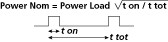
Where: Power
Nom. = Nominal transformer rating
Power Load =
Actual power in the load
t on = Load on time
t tot
= Total cycle time |
| |
| Guide To Transformers - Operating
Frequency |
|
|
The operating
frequency determines the transformer size and weight for
a given output power-higher frequency generally means a
smaller transformer.
A transformer designed
for 60 Hz operation only will therefore be smaller and
lighter than one designed for 50/60 Hz operation, though
this size reduction will not be considerable for a
difference of only 10 Hz. However, a transformer for 400
Hz operation may be up to 80% smaller than a 50/60 Hz
transformer. It is important to specify the minimum
expected operating frequency of transformers, as
operation is possible above the designed frequency but
not below. |
| |
| Guide To Transformers - Primary
Configuration |
|
|
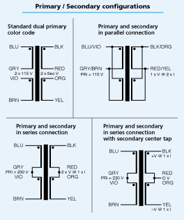
| It is
preferable to try to obtain the required secondary
voltages using separate identical primaries to be used
in series or parallel. For example, two identical 115v
50 Hz primaries would be connected in series to obtain
230v 50 Hz, or in parallel to obtain 115v, 50 Hz. This
arrangement is the most economical in both price and
transformer size. A more versatile arrangement would be
2 identical primaries of, for example, 0-100-115V. This
will provide 100, 115, and 230V, covering input voltages
for places such as Japan, USA, and Europe.
(The unused taps must then
be insulated well, as these will be at their stated
voltages above ground and to the other windings when the
transformer is in use.)
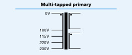
Another option (which
generally requires a larger and more expensive
transformer), is a multi-tapped or ladder
primary.
|
| |
| Guide To Transformers - Primary
Voltage |
|
|
| The Primary
voltage(s) stated in standard transformer specifications
(or customer-specified in an inquiry) are the nominal
voltages. These voltages may vary during times when line
supplies are at heavy loads (nearly always around
dinnertime), or light loads (when most people are
asleep). Drops or rises in this voltage can be as much
as 10% of the nominal and vary considerably from country
to country. This change in voltage will be reflected on
the secondary voltage (on and off-load) by the standard
transformation relationship:

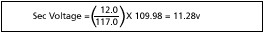
Example:
A toroidal transformer is rated at
12v and the primary is rated at 117v 60 Hz. The line
supply regulation is stated as ± 6% by the utility
company.
The secondary voltage when
the line is at its lowest voltage will be:
|
| |
| Guide To Transformers -
Regulation |
|
|
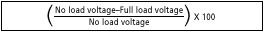
Transformer
regulation is a measure of the voltage rise on the
secondary due to off-load or light-load conditions with
the primary input voltage remaining constant. This
measure is expressed as a percentage of the secondary
voltage; for example, a transformer with 10% regulation
and rated at 12v at full load will have an off-load
voltage of 13.2v.
Regulation is calculated
as:
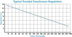
Due to the design
characteristics of transformers, regulation varies
inversely with power rating (VA) and is approximately
linear for any given loading on the secondary. In the
above example, if the load was 50% of full load, the
voltage would be 5% higher, or 12.6v. This regulation
figure must be borne in mind when designing rectifier
power supplies, etc. as it will affect the voltage
rating of reservoir capacitors, voltage regulators,
etc.
Custom transformers can be designed with
very low regulation figures but only at the expense of
size and weight, as larger cores and wire gauges must be
used. Following are some typical regulation figures for
standard transformer VA ratings.
|
| |
| Guide To Transformers - Temperature
Rise |
|
|
Avel's standard
toroidal transformers are designed for a temperature
rise of a maximum of 60ºC, and have a material rating of
Class A (105ºC), although the winding wire used has a
rating of Class F (155ºC) for additional reliability.
This temperature rise is above the ambient temperature
of approximately 30-35ºC.If a higher temperature rise
can be tolerated by surrounding components and
enclosures, then a reduction in transformer size may be
considered.
Avel can manufacture to most
standard temperature classes, although the cost of the
transformer will rise considerably due to the
higher-cost materials that would be required. It is
important to furnish expected ambient temperatures in a
custom inquiry for any temperature class, as the running
temperature of the transformer will be the ambient
temperature plus the transformer temperature
rise.
Below are some standard
temperature classes.
Insulation
Classes:
- Y = 90º C
- A = 105º C
- E = 120º C
- B = 130º C
- F = 155º C
- H = 180º C
|
| |
| Guide To Transformers - Capacitive
Shielding |
|
|
Transformers by
nature are wide band devices regarding stray signal
coupling. Where a transformer is required to operate in
electrically noisy environments, a conducting shielding
layer can be interposed between the primary and
secondary windings (or between individual secondaries)
to minimize the capacitance between them. This can
reduce (or even eliminate) some types of common mode
noise, but its effectiveness depends on the noise
characteristic as well as the transformer's overall
surface area.
This type of shield is
sometimes required to satisfy certain safety regulations
and circuit configurations. Capacitive screens add
layers and cost to a toroid's build, because if they are
required, a larger core may have to be specified with a
large enough inner diameter to complete the windings.
This type of shielding should supplement and not replace
the usual line filters and suppressor networks that may
be required for circuit operation or EMC
compliance. |
| |
| Guide To Transformers - Magnetic
Shielding |
|
|
Although
toroidal transformers emit minimal stray magnetic fields
by their nature, a certain amount will always be present
as with all magnetic devices. For the vast majority of
applications, toroidal emissions are far too low to
affect circuit operation, but there are some
applications that are especially sensitive.
These
include wideband, high-gain instrumentation and
preamplification, high-end audio, and high-resolution
CRT circuits. In this case, magnetic shielding can be
applied around the toroid in the form of a
high-permeability metal band. This can be Silicon Steel
for the majority of cases or Mu Metal for sensitive
applications. For extremely sensitive circuits, total
encapsulation in a steel can or case may be the only
option. There are ways to reduce emissions by design
(before any protection is added to the transformer), so
if your circuit is prone to magnetic interference,
please include this information in specifications when
requesting a quotation. |
| |
| Guide To Transformers - Inrush
Currents |
|
|
| Due to the
excellent magnetic circuit that toroidal cores create,
and also due to the remanence that results from the more
square hysteresis loop that these cores possess, high
inrush currents can be encountered when switching on
large toroidal transformers. These are higher than in
laminated stack transformers and can last for a few
half-cycles of the mains voltage. This is caused by the
core saturating for a split second and is quite normal.
However, this means that larger toroidals (1.5 KVA and
higher) should not be switched on without some
precautions.
It is recommended that
slow-blow (type T) fuses be used in the primary circuits
of all transformers over 100 VA. For larger toroids,
either NTC thermistors or circuit breakers designed for
motors and transformers (with type D delay
characteristics, for example) should be incorporated.
Simple relay-switched resistor soft start circuits can
also be used effectively, and a delay of between about
30 to 300 mS will usually work effectively (some relays
themselves have pull-in delays of approximately this
time). Soft start circuits of this kind should be
implemented with, and never replace, the proper circuit
protection provided by fuses or circuit breakers.
|
| |
| Guide To Transformers - Mounting
|
|
|
The standard
method of mounting toroidal transformers to a chassis is
with a dished steel washer, with the transformer
interposed between cushioning gaskets, with this
hardware held in place by a single bolt passed through
the central hole of the toroid. These mounting kits are
supplied with standard transformers. For other mounting
options, please see the custom
transformers.
Caution: The metal chassis should
not touch both ends of the mounting bolt. This causes a
shorted turn, which would overheat the transformer
rapidly and cause its destruction. |
| |
| Guide To Transformers - Varnishing
and Vacuum Impregnation |
|
|
| Avel offers
full vacuum and pressure varnish impregnation, as well
as envelope dipping with mold-resistant polymers and
protective barriers. Impregnation and dipping can be
carried out with either standard solvent-based coil
varnishes or solventless epoxy varnishes. Contact Avel
for further information, or where you feel you may have
an unusual environmental requirement. |
| |
| Guide To Transformers - Thermal
Protection |
|
|
| Thermal
protection can be built in to our toroidal transformers
in the form of thermal sensitive fuses and switches
(thermostats). These protectors are generally built
inline into the primary winding, and are in close
thermal contact with the windings. Thermal fuses are not
resettable and once blown cannot be replaced. Thermal
switches are designed to open at a set temperature and
will close again upon cooling, reforming the primary
circuit (with slight hysteresis). These protectors may
be required to satisfy certain safety approvals.
Customer specified protection can be added in the form
of Normally Open switches, as well as incorporation into
specific windings. Thermal protection always adds to the
cost of toroidals and can affect the transformer
geometry slightly. Our engineers are pleased to advise
on protection issues. |